Table of Contents >> Show >> Hide
- Before You Start: Blueprints vs. “A Nice Drawing”
- Step 1: Collect the Info Your Blueprint Must Answer
- Step 2: Understand What Your Permit Office Typically Wants
- Step 3: Choose Your Tools (Hand Drafting or Software)
- Step 4: Pick a Scale and Stick to It Like Glue
- Step 5: Measure and Draw the Site Plan First
- Step 6: Create a Bubble Diagram and Rough Layout
- Step 7: Draw the Floor Plans (The Main Event)
- Step 8: Draw Exterior Elevations
- Step 9: Add Building Sections and Key Details
- Step 10: Think About Structure and MEP (Even If You’re Not Drawing It All)
- Step 11: Use Line Weights, Notes, and Sheet Organization Like a Pro
- Step 12: Quality-Check Your Plans Before Anyone Else Does
- Common Mistakes (So You Can Avoid Them and Feel Smug Later)
- Conclusion: Your Blueprint Is a Communication Tool, Not a Work of Art
- Experiences: What It Feels Like to Actually Draw House Blueprints (The Good, the Humbling, and the Funny)
- SEO Tags
“Blueprints” sounds like something you need a secret handshake to access. In reality, house blueprints are just a
clear set of drawings that explain what you’re building, where it goes on the lot, and how it
fits together so your builder (and your building department) don’t have to play interpretive dance with your ideas.
This guide walks you through drawing house plans the right waywhether you’re sketching by hand on graph paper or
using design software. You’ll learn what drawings belong in a typical plan set, how to pick a scale, how to use
standard symbols, and how to avoid the classic “my hallway is 17 inches wide” moment.
Before You Start: Blueprints vs. “A Nice Drawing”
A pretty floor plan is great for dreaming. A blueprint (often called a permit set or
construction drawings) is what lets you actually buildand get approved. Many jurisdictions accept a
“minimum” plan set for a permit, while a contractor-friendly set usually adds more detail (and saves money by
preventing mid-build surprises).
Reality check: you may need a licensed pro
Local rules vary. Some areas allow homeowners to submit their own drawings for certain projects; others require
plans prepared or stamped by a licensed architect or engineerespecially for new homes, structural changes, or
complex sites. Always verify requirements with your local building department before you invest a week drawing the
world’s most beautiful staircase.
Step 1: Collect the Info Your Blueprint Must Answer
Good plans don’t start with lines. They start with questions. Create a simple “design brief” that covers:
- Goals: new build, addition, remodel, ADU, garage, etc.
- Space needs: bedrooms/baths, office, storage, laundry, mudroom, pantry, garage bays.
- Style & function: open concept vs. defined rooms, aging-in-place, accessibility, kids/pets.
- Budget constraints: must-haves vs. nice-to-haves.
- Site constraints: slopes, trees, easements, flood zones, utilities, driveway location.
Gather existing documents
If you’re remodeling or adding on, grab any existing plans, surveys, and a recent property plat. If you don’t have
those, measure carefully. Your future self will thank you when you’re not discovering a mysterious 9-inch “bonus
wall” after framing.
Step 2: Understand What Your Permit Office Typically Wants
Most residential plan submissions revolve around a familiar core:
site plan, floor plans, elevations, and
sections. Depending on the project, you may also need structural notes, foundation details,
energy compliance docs, and mechanical/electrical/plumbing (MEP) information.
Even if you’re not applying for a permit yet, drawing with permit requirements in mind forces clarityand clarity
is what prevents expensive rework.
Step 3: Choose Your Tools (Hand Drafting or Software)
Hand drafting basics
- Graph paper (or drafting paper)
- Architectural scale ruler
- Mechanical pencils + eraser (the unsung hero of design)
- Straightedge/ruler, triangles, compass (optional but satisfying)
Software options
If you want clean output fast, use floor plan software or CAD/BIM tools. Many programs can generate elevations,
schedules, and even 3D views. The key is not which program you pickit’s whether your drawings are accurate,
consistent, and properly scaled.
Step 4: Pick a Scale and Stick to It Like Glue
A blueprint must be drawn to scale. In the U.S., a common residential floor plan scale is
1/4″ = 1′. Site plans are often smaller scale (so the whole lot fits) such as 1″ = 10′
or similar, depending on local standards and lot size.
Quick scale example (so your math doesn’t haunt you)
If your living room is 16 feet long and you draw at 1/4″ = 1′, then 16 feet becomes 4 inches on paper.
(Because 16 × 0.25″ = 4″.) This is why architects carry scale rulers like wands.
Step 5: Measure and Draw the Site Plan First
Your site plan is a scaled overhead drawing of your property that shows where the house sits on the
lot. This is where setbacks, easements, and driveways liveaka the stuff that decides whether your project is
approved or sent back with a polite note that ruins your weekend.
Site plan essentials (typical checklist)
- Property lines with dimensions
- Street name, north arrow, and scale
- Existing structures and the proposed structure footprint
- Setbacks from property lines
- Driveway, sidewalks, parking
- Utilities (water, sewer/septic, electrical, gas), easements if known
- Topography/grade direction if relevant (especially on slopes)
Tip: If you’re working from a survey, treat it like gold. If you’re not, measure twice and assume your fence line
is lying to you (because it might be).
Step 6: Create a Bubble Diagram and Rough Layout
Before you draw walls, sketch a “bubble diagram”simple circles/blocks for rooms and how they connect. This keeps
you from locking yourself into a bad layout just because you drew a really confident rectangle.
Layout rules that save headaches
- Keep plumbing areas near each other (kitchen + baths) to reduce long pipe runs.
- Think about daylight: where will your best windows face?
- Plan circulation: avoid hallways that feel like airport jet bridges.
- Consider furniture early so you don’t build a bedroom that only fits a bed if you fold it like origami.
Step 7: Draw the Floor Plans (The Main Event)
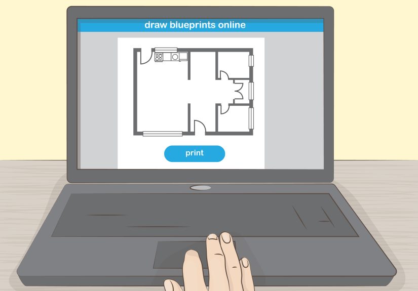
Floor plans are the top-down drawings of each level showing walls, doors, windows, fixtures, and dimensions. A
solid floor plan typically includes:
What to include on your floor plan
- Exterior and interior walls (with consistent thickness)
- Room names (Kitchen, Bedroom 2, Pantry, etc.)
- Door swings and window locations
- Stairs with direction (up/down) and key dimensions
- Built-ins, cabinets, plumbing fixtures, and major appliances (as needed)
- Dimensions: overall building, key room sizes, and critical offsets
- Notes: ceiling heights, special conditions, smoke/CO alarms if required by your locale
Dimensioning that won’t get you yelled at (politely)
Use a consistent approach: outermost dimensions for overall building size, then intermediate dimensions for wall
segments/openings, then interior room dimensions if needed. Keep dimensions readablecrowded dimension strings are
the blueprint equivalent of whispering directions during a hurricane.
Use standard symbols
Doors are typically shown with a swing arc. Windows have standard simplified symbols. Add a legend if you use
anything unusual. Your goal is for someone else to read your plan without calling you every 12 minutes.
Step 8: Draw Exterior Elevations
Elevations show what the house looks like from the outside (front, rear, left, right). They typically include:
- Roof shape and slopes
- Door and window sizes/locations
- Exterior materials (siding, stone, stucco, etc.)
- Overall heights and key vertical dimensions
- Grade/ground line and how the building meets the site
Elevations are where your cute “modern farmhouse” idea becomes an actual buildable façadeso label materials and
heights clearly.
Step 9: Add Building Sections and Key Details
A section is a cut-through view that shows how floors, walls, roof, and foundation stack up. Most
plan sets include at least one or two sections, plus enlarged details where needed (stairs, roof eaves, foundation,
tricky transitions).
Why sections matter
Floor plans show “where.” Sections show “how.” They clarify ceiling heights, roof framing space, insulation areas,
floor thicknesses, and structural relationshipsespecially important for permits and construction.
Step 10: Think About Structure and MEP (Even If You’re Not Drawing It All)
For a full construction set, structural framing plans (foundations, floor/roof framing), and MEP plans may be
required. Even if you’re only producing preliminary plans, you should plan for:
- Load paths: where roof and floor loads travel down to the foundation
- Big openings: large windows/doors often need engineered headers or beams
- Mechanical space: HVAC equipment, ducts, chase walls, returns
- Plumbing routes: stacks, venting, and avoiding impossible pipe runs
- Electrical planning: panel location, kitchen circuits, lighting logic
Translation: if you design a house with nowhere to run ducts, you’ll eventually “discover” a soffit you didn’t
budget for. Surprise soffits are rarely charming.
Step 11: Use Line Weights, Notes, and Sheet Organization Like a Pro
A readable blueprint isn’t just accurateit’s communicative. That’s where drafting conventions
come in:
Line weights (aka: the secret language of thickness)
- Heavier lines typically show elements being cut (like walls in plan view).
- Lighter lines show things beyond (cabinets, fixtures, overhead items).
- Dashed lines often indicate items above or hidden conditions.
Title block and sheet info
Most drawing sets use a title block with project name/address, sheet title/number, scale, date, and revision info.
If your drawings are multiple pages, create a sheet index so reviewers and builders can find what they need quickly.
Consistent sheet numbering
Many U.S. drawing sets follow standardized sheet identification conventions (discipline + sheet type + sequence).
You don’t need to be obsessivebut you do need to be consistent. Confusing sheets waste time, and time is money
(and sometimes also your contractor’s patience).
Step 12: Quality-Check Your Plans Before Anyone Else Does
Do a “red-pen review” on yourself. Check:
- All drawings have scale noted (and are actually drawn to that scale).
- Dimensions add up and don’t contradict each other.
- Door swings make sense (no doors smashing into toilets).
- Stairs have realistic rise/run and adequate headroom.
- Windows/doors align logically between plan and elevations.
- Site plan setbacks are clearly shown and compliant.
- Notes are legible and not tiny ant-writing.
A simple example walkthrough (tiny but real)
Say you’re planning a basic 28′ × 40′ single-story home. At 1/4″ = 1′, your exterior footprint becomes 7″ × 10″ on
paper. You’d start by drawing the footprint, then place interior partitions, then dimension overall and key
segments. Next, you’d draft elevations with window heights and roof pitch, then add at least one section to show
foundation, wall, and roof assembly relationships. Finally, you’d confirm setbacks on the site plan based on your
lot dimensions. That’s a permit-friendly backbonethen you can add details as needed for construction.
Common Mistakes (So You Can Avoid Them and Feel Smug Later)
- Not drawing to scale: “It’s basically 12 feet” isn’t a blueprint measurement.
- Skipping the site plan: setbacks and easements can kill a design instantly.
- Undersized circulation: hallways, stairs, and door clearances matter every day.
- Forgetting thickness: walls aren’t theoretical; they take up real space.
- Unclear drawings: messy notes and inconsistent symbols lead to expensive assumptions.
- No coordination: if the plan shows one thing and the elevation shows another, the builder will pick… and you may not like their choice.
Conclusion: Your Blueprint Is a Communication Tool, Not a Work of Art
Yes, a clean plan set is satisfying. But the real win is that your drawings communicate clearly enough that permits
move faster, bids are more accurate, and construction doesn’t turn into a daily Q&A session. Start with the site
and requirements, draw everything to scale, use standard symbols, and check your work like you’re grading your own
exam. (Because you kind of are.)
Experiences: What It Feels Like to Actually Draw House Blueprints (The Good, the Humbling, and the Funny)
People often expect the “experience” of drawing house blueprints to feel like a cozy HGTV montage: coffee mug,
peaceful music, a few elegant lines, and suddenly you’re standing inside your future home basking in golden hour
light. In real life, the process is more like: excitement → confidence → mild confusion → bargaining → enlightenment.
One common experience is the Scale Shock. On day one, a 16′ room seems normal. On the paper, it’s
four inches long, and suddenly your entire life is being translated into stationery. That’s when people learn to
love the architectural scale ruler. There’s a genuine “aha” moment the first time you place rooms at true scale and
realize: “Oh. My dream kitchen island is not a personality trait. It is a measurement problem.”
Another classic experience is the Hallway Reality Check. Many first-time drafters draw hallways too
narrow because they’re thinking visually instead of physically. Then they imagine walking down that hallway
carrying a laundry basket, passing another person, and trying not to scuff the walls. That little mental role-play
turns into an immediate redesignand it’s one of the best lessons blueprinting can teach: a house isn’t a drawing,
it’s a daily routine you move through.
People also run into the Door Swing Comedy Hour. Doors are sneaky. They’re rectangles with opinions.
You draw a door, add a swing arc, and suddenly two doors are fighting for the same square foot like it’s the last
parking spot at the mall. This is where blueprinting becomes oddly satisfying: you catch silly conflicts on paper,
not after you’ve paid someone to install the world’s most inconvenient linen closet.
A big emotional milestone is when the site plan enters the chat. Many homeowners describe this moment as,
“Waitmy lot has rules?” Setbacks, easements, driveway slopes, and protected trees can feel like the
universe is personally attacking your floor plan. But it’s also empowering. Once you experience how site constraints
shape design, your priorities get sharper. You stop wasting time designing a rear addition that can’t legally sit
where you want it, and you start finding smarter solutionslike shifting the footprint, rotating the layout for
better access, or reshaping rooms to stay compliant.
There’s also the experience of Learning to Think in Layers. At first, floor plans feel like the
whole story. Then you add elevations and realize you’ve placed a huge window right where a sloped roof drops low.
Then you add a section and understand how ceiling heights, roof structure, and foundation depth connect. Many
people describe this as the point where blueprinting stops being “drawing” and becomes “design thinking.” You’re no
longer sketching roomsyou’re coordinating an entire system.
Finally, almost everyone who drafts plans has a moment of Unexpected Respect for the pros. Not
because you can’t do itbecause you absolutely can learn the basicsbut because you realize how many details must
align: codes, structure, energy requirements, clearances, grading, drainage, and the reality of construction. That
respect is valuable. It makes you a better collaborator if you hire an architect or engineer, and it makes your own
drawings stronger because you’re thinking beyond “Does it look nice?” to “Can someone build this safely, legally,
and predictably?”
If you take anything from these shared experiences, let it be this: the goal isn’t perfection on the first draft.
The goal is a clear, scaled, coordinated plan that gets better each iteration. Blueprints are permission to be
wrong cheaplyon paperso you can be right when it matters, on the job site.