Table of Contents >> Show >> Hide
- Why Convert a Robotic Motor for LEGO Blocks?
- Understanding the LEGO Technic Connection System
- Choosing the Right Robotic Motor
- Planning the Mechanical Adapter
- Designing the Gear Ratio
- Powering the Converted Motor
- Building a Simple LEGO-Compatible DC Gearmotor Adapter
- Common Mistakes to Avoid
- Best Projects for Converted Robotic Motors
- Safety and Durability Tips
- Real-World Experience: What You Learn When Converting Motors for LEGO Blocks
- Conclusion
LEGO builds are already excellent at turning a kitchen table into a miniature engineering lab. Add a robotic motor, and suddenly your charming little crane, rover, conveyor belt, or suspiciously overpowered snack-delivery machine starts behaving like a real robot. The challenge is that most hobby robotics motors are not designed to snap directly into LEGO Technic beams. They arrive with round shafts, metal gearboxes, mounting holes in strange places, and wires that look as if they escaped from a tiny science-fiction movie.
That is where motor conversion comes in. Converting a robotic motor for LEGO blocks means adapting a non-LEGO motor so it can physically connect, mechanically drive, and electrically behave inside a LEGO-based model. This can involve a shaft adapter, a custom bracket, a 3D-printed mount, a coupler, gears, a motor driver, or all of the above if your project has the personality of a caffeinated raccoon.
The good news: you do not need a full machine shop to make it work. With careful measuring, basic robotics knowledge, and a little respect for torque, you can combine LEGO Technic parts with DC gearmotors, servos, stepper motors, and microcontroller-based systems. The result is a build that keeps the modular fun of LEGO while gaining the strength, speed, precision, or affordability of common robotic motors.
Why Convert a Robotic Motor for LEGO Blocks?
LEGO already offers excellent motorized systems, including Powered Up, Technic hubs, SPIKE Prime motors, and older Power Functions components. These official parts are clean, reliable, and beautifully integrated into the LEGO building system. A Technic hub can connect to motors, lights, and sensors through multiple ports, and Powered Up components can bring movement, Bluetooth control, and programmable behavior to custom creations.
So why use an outside motor at all? Usually, the answer comes down to cost, availability, power, size, or experimentation. Hobby robotic motors are easy to find in many shapes and specifications. A small DC gearmotor may be perfect for a lightweight rover. A metal-geared servo may be better for a robotic arm joint. A stepper motor may be useful when you need precise incremental movement. A high-torque gearmotor may be the right choice when your LEGO model has to lift something heavier than a polite suggestion.
Converting a motor also teaches real engineering. You learn how rotational speed, torque, gear reduction, shaft alignment, friction, backlash, voltage, current, and structural bracing all interact. LEGO blocks make prototyping friendly, while robotics motors make the project more powerful and flexible. Together, they create a hands-on bridge between toy-scale creativity and practical mechanical design.
Understanding the LEGO Technic Connection System
The key to motor conversion is understanding how LEGO Technic transfers motion. Traditional LEGO bricks rely on studs and tubes. Technic builds rely on beams, pins, axles, gears, bushings, liftarms, and frames. For motor projects, the Technic axle is the star of the show. It has a cross-shaped profile that fits gears, wheels, pulleys, sprockets, and connector pieces without slipping under normal loads.
Most non-LEGO robotic motors, however, use round shafts, D-shaped shafts, splined servo outputs, or threaded shafts. That means the motor cannot simply grab a LEGO gear unless you adapt the output. Your conversion must solve two jobs: first, hold the motor body firmly in the LEGO structure; second, transfer rotation from the motor shaft into a LEGO axle or gear without wobbling, slipping, or chewing parts like a tiny plastic beaver.
The Three Main Conversion Problems
Mounting: The motor needs a stable frame. If the motor twists every time it starts, your gears will separate, your model will flex, and your robot will develop what engineers call “unplanned interpretive dance.”
Shaft coupling: The spinning shaft must connect to LEGO parts. This may require a metal coupler, a 3D-printed axle adapter, a set-screw hub, or a flexible coupling.
Power and control: The motor needs the right voltage, current, and controller. A LEGO hub is not designed to power random high-current motors directly. In many cases, you will use an external battery, motor driver, and microcontroller such as an Arduino-compatible board.
Choosing the Right Robotic Motor
Before you build an adapter, pick the motor carefully. The wrong motor can make even a beautiful LEGO chassis behave like a shopping cart with one haunted wheel.
DC Gearmotors
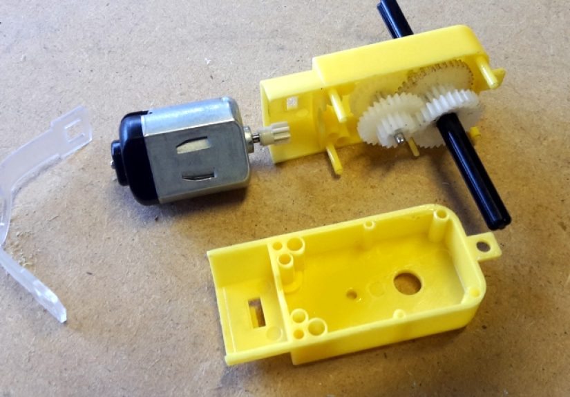
DC gearmotors are one of the most common choices for LEGO conversions. A plain DC motor usually spins too fast and has too little torque for direct use. A gearmotor adds an internal gearbox that reduces speed while increasing torque. This makes it more useful for LEGO vehicles, conveyors, winches, turntables, and mechanical displays.
Look for specifications such as rated voltage, no-load speed, stall current, stall torque, shaft diameter, gearbox ratio, and mounting pattern. For LEGO-scale projects, compact 3V to 12V gearmotors are often practical. Choose a slower motor for lifting or pushing. Choose a faster motor for lightweight vehicles. If the project needs control in both directions, use an H-bridge motor driver so the motor can run forward and reverse.
Servo Motors
Servos are useful when you need controlled angular movement rather than endless spinning. Standard hobby servos typically rotate through a limited range, often around 180 degrees, and are controlled by simple pulse signals from a microcontroller. This makes them excellent for steering, robotic claws, levers, gates, and small arms.
A servo can be converted for LEGO by attaching a LEGO-compatible horn or adapter to the servo output. Some makers use 3D-printed servo-to-Technic adapters; others drill a LEGO-compatible connector and screw it to the servo horn. Be careful here: drilling actual LEGO pieces is permanent, mildly heartbreaking, and may upset purists within a five-mile radius. If possible, modify a spare part or use a custom adapter instead.
Continuous Rotation Servos
A continuous rotation servo looks like a regular servo but behaves more like a geared DC motor with built-in control electronics. Instead of commanding a position, you command speed and direction. This can be useful for small LEGO vehicles or spinning mechanisms, but it is generally less precise than a true positional servo.
Stepper Motors
Stepper motors move in small increments, making them attractive for precise positioning. They are useful for camera sliders, turntables, plotters, and mechanisms that need repeatable motion. However, steppers usually require dedicated drivers, proper current control, and stronger mounting. They can also be heavier than typical LEGO motors, so your frame needs extra reinforcement.
Planning the Mechanical Adapter
The best adapter is not always the prettiest one. It is the one that keeps the motor aligned, transfers torque cleanly, and avoids stressing the LEGO parts. Start by measuring the motor shaft. Common small motors may use 2mm, 3mm, 4mm, or 6mm shafts. Some have a D-shaped profile, which helps a set screw grip. Others are round and may need a clamp-style coupler.
Next, decide how the motor will connect to the LEGO drivetrain. You have several practical options.
Option 1: Shaft Coupler to LEGO Axle
The cleanest approach is a coupler that accepts the motor shaft on one side and a LEGO Technic axle on the other. A metal coupler with a set screw can hold the motor shaft tightly. The LEGO side can be created with a custom 3D-printed insert, a machined cross-shaped socket, or a modified compatible hub.
This method is strong and compact, but alignment matters. If the motor shaft and LEGO axle are not centered, the drivetrain will wobble. Wobble increases friction, wears parts, and makes the mechanism sound like it is quietly judging you.
Option 2: Motor Shaft to Gear or Pulley
Instead of driving a LEGO axle directly, the motor can spin a small gear, pulley, or wheel that transfers motion to a LEGO gear train. This approach is more forgiving if the motor shaft does not match LEGO geometry. For example, a rubber wheel on the motor shaft can press against a LEGO wheel to create a friction drive. A timing pulley can drive a belt. A small pinion gear can mesh with a LEGO gear if the spacing is carefully designed.
The downside is that friction drives can slip, and mixed gear systems can be noisy if the tooth profiles do not match. Use this approach for experiments, low-load models, and quick prototypes rather than heavy-duty machines.
Option 3: 3D-Printed Motor Mount
For many builders, 3D printing is the magic wand. A printed mount can include Technic pin holes, screw holes for the motor, and a centered shaft opening. It can hold a DC gearmotor, servo, or stepper motor in a LEGO-compatible frame.
When designing a mount, respect LEGO spacing. Standard LEGO geometry is based on an 8mm horizontal grid, while Technic holes align to that modular system. If your printed holes are slightly off, the part may technically fit but still create stress. That stress can make beams bow, gears bind, and your robot look as if it skipped leg day.
Use strong materials such as PETG, ABS, nylon, or high-quality PLA for light-duty builds. Print with enough wall thickness and infill around screw holes. If the motor has significant torque, include bracing points on both sides of the output shaft.
Designing the Gear Ratio
Motor conversion is not only about making parts fit. It is also about making the motion useful. A motor that spins too fast can shred a LEGO gear train or send your rover into the baseboards like it has unresolved feelings. A motor that spins too slowly may be strong but boring.
Gear reduction reduces speed and increases torque. For example, if a motor output is too fast, you can use LEGO gears to reduce speed further. A small gear driving a larger gear reduces speed and increases torque. A large gear driving a smaller gear increases speed but reduces torque. For lifting arms, cranes, walkers, and heavy vehicles, gear down. For fans, light vehicles, and spinning displays, you may gear up carefully.
Also consider backlash, which is the small amount of play between gear teeth. Backlash is normal, but it can reduce precision in robotic arms or positioning systems. Worm gears can prevent back-driving and are useful for lifting, but they add friction. Bevel gears change direction of rotation, but they need solid bracing to stay meshed.
Powering the Converted Motor
One of the most important rules is simple: do not assume a LEGO hub can safely power a random motor. Official LEGO electronics are designed for LEGO components. A high-current motor can draw far more power than the hub expects, especially when stalled. Stall current happens when the motor shaft is prevented from rotating while power is applied. This is where motors get hot, drivers complain, batteries sag, and smoke may attempt to become part of the project.
For non-LEGO motors, use a suitable motor driver. A brushed DC motor usually needs an H-bridge driver. A servo usually needs a stable power supply and signal line from a microcontroller. A stepper motor needs a stepper driver matched to its voltage and current requirements. Always check the motor’s rated voltage and stall current, then choose a driver with comfortable overhead.
Basic Control Setup
A typical converted LEGO robotics setup may include:
- A LEGO Technic frame or model
- A robotic motor mounted with a bracket or adapter
- A shaft coupler or gear interface
- An external battery pack matched to the motor
- A motor driver board
- A microcontroller for speed, direction, or position control
- Optional sensors, such as encoders, limit switches, or distance sensors
If your motor has an encoder, you can measure rotation and create closed-loop control. This helps a robot drive straighter, stop more accurately, or maintain speed under load. Without feedback, the motor can still run well, but the system will not know exactly how far it moved unless you add sensors.
Building a Simple LEGO-Compatible DC Gearmotor Adapter
Here is a practical example. Suppose you want to convert a small metal DC gearmotor for a LEGO rover.
Step 1: Measure the Motor
Measure the shaft diameter, shaft length, gearbox body, and mounting holes. Also note whether the shaft is round or D-shaped. A D-shaped shaft is easier to grip with a set screw because the flat side prevents slipping.
Step 2: Choose the Output Connection
For a rover, the most useful connection is usually motor shaft to LEGO axle. Use a coupler that grips the motor shaft and holds a Technic axle as straight as possible. If you are designing a 3D-printed coupler, leave enough wall thickness around the cross-shaped socket so it does not split under torque.
Step 3: Create the Mount
Design or assemble a bracket that attaches to Technic beams at multiple points. Avoid mounting the motor from only one side if the load is high. A motor works like a tiny torque wrench; when the shaft turns one way, the body wants to twist the other way. Your bracket must resist that twist.
Step 4: Add Gear Reduction if Needed
If the rover moves too fast or stalls on carpet, gear it down. A smaller driving gear connected to a larger driven gear can improve torque. For rough terrain, slower and stronger is usually better than fast and dramatic.
Step 5: Test at Low Power
Run the motor slowly first. Watch for wobble, gear skipping, heat, bending beams, and slipping couplers. Do not start with full power unless you enjoy collecting plastic gears from across the room.
Common Mistakes to Avoid
Using Too Much Torque
LEGO parts are strong for plastic toys, but they are not industrial drive components. A powerful metal gearmotor can twist axles, spread liftarms apart, strip gears, or crack custom printed adapters. If your motor is strong enough to make the model lurch violently, reduce power, gear down carefully, or add a clutch mechanism.
Ignoring Shaft Alignment
Misalignment is one of the fastest ways to ruin an otherwise clever conversion. The motor shaft and driven LEGO axle should be coaxial when direct-coupled. If they are slightly off, use a flexible coupler or redesign the mount.
Forgetting About Current Draw
A motor may look tiny and innocent, but under stall conditions it can draw several times its normal running current. Always size the motor driver and battery for the real load, not just the no-load current. If your driver gets hot quickly, the motor stalls, or the battery voltage collapses, stop and troubleshoot.
Building a Weak Frame
Motor mounts need triangulation, bracing, and multiple connection points. LEGO Technic frames can be very rigid when designed well, but long unsupported beams flex. Add frames, perpendicular bracing, and cross supports around the motor.
Best Projects for Converted Robotic Motors
A converted robotic motor can upgrade many LEGO builds. Some of the best projects include:
- Rovers: Use DC gearmotors for stronger drive systems and larger wheels.
- Robotic arms: Use servos for shoulder, elbow, wrist, and claw movement.
- Turntables: Use steppers or geared motors for smooth rotating displays.
- Conveyor belts: Use slow gearmotors for steady motion.
- Automated doors: Use servos or worm-geared motors for controlled opening.
- Mini cranes: Use high-torque motors with worm gears or pulleys.
- STEM demos: Use LEGO frames to teach gear ratios, load testing, and feedback control.
Safety and Durability Tips
Always test converted motors with the model elevated or unloaded first. Keep fingers away from gears, especially when using high-torque motors. Add a power switch that is easy to reach. Use fuses or current-limited power supplies for experimental setups. Keep wiring neat so it does not wrap around axles. If the motor smells hot, it is not “breaking in.” It is asking for mercy.
For durability, use bushings on both sides of loaded gears. Support long axles at multiple points. Avoid cantilevering heavy wheels directly from a motor shaft unless the motor gearbox is designed for side loads. In many cases, it is better for the motor to drive a LEGO axle that is separately supported by Technic beams.
Real-World Experience: What You Learn When Converting Motors for LEGO Blocks
The first lesson is that LEGO is honest. If your design is weak, it will tell you immediately. Gears skip. Beams flex. Axles walk out of connectors. A motor mount that looked perfectly reasonable on the desk suddenly twists under load like a pretzel auditioning for a snack commercial. This is not failure; it is feedback with sound effects.
One of the most useful experiences is learning to test in stages. Do not build the entire robot and then discover the motor is too fast, too weak, or mounted slightly crooked. Start with the motor and adapter alone. Spin the shaft slowly. Add one gear. Then add the axle supports. Then add the load. Each stage reveals a different problem. A direct coupler might work beautifully with no load but slip when the wheels touch carpet. A bracket might hold during forward motion but twist when the motor reverses. A gear train might run smoothly by hand but bind under power because the beams spread apart.
Another big lesson is that torque needs a path. Beginners often focus on the spinning shaft and forget the motor body. When a motor turns a wheel, the motor case experiences an equal reaction force. If the mount is weak, that force goes into the LEGO frame and causes flex. The cure is usually more bracing, shorter spans, and mounting points on both sides. In LEGO Technic building, stiffness is often more valuable than raw power.
You also learn that speed is overrated. A fast LEGO robot is fun for about three seconds, right up until it misses a turn, skips gears, and launches a decorative panel into another ZIP code. Slower gearing gives better control, better torque, and better reliability. For most practical builds, a smooth slow motor feels more professional than a wild fast one.
3D printing adds another layer of experimentation. A printed adapter that fits perfectly in software may be too tight in real life because printers have tolerances. Holes may need slight clearance. Thin walls may crack around set screws. Layer direction matters: a coupler printed in the wrong orientation can split along layer lines. After a few prototypes, you start designing parts with thicker hubs, rounded corners, reinforced screw zones, and enough clearance for LEGO pins to seat without stress.
Electrical testing teaches humility too. A motor that runs happily in the air can pull much more current when pushing a vehicle, lifting an arm, or stalling against an obstacle. Good builders check heat, driver ratings, wire thickness, and battery performance. They also add code limits, soft starts, and emergency stops. The goal is not just movement; it is controlled movement that does not cook the electronics.
The most satisfying moment comes when the adapted motor finally disappears into the model. The bracket is solid, the coupler runs true, the gears mesh cleanly, and the LEGO creation moves as if the motor belonged there all along. That is the reward: a hybrid machine that keeps the playful snap-together spirit of LEGO while borrowing strength and control from robotics hardware.
Conclusion
Converting a robotic motor for LEGO blocks is part engineering project, part puzzle, and part negotiation with plastic geometry. The job is not simply to attach a motor. The real goal is to create a reliable connection between a robotic power source and the LEGO Technic building system. That means choosing the right motor, designing a strong mount, adapting the shaft, controlling power safely, and testing the drivetrain under realistic loads.
For simple models, a small DC gearmotor with a coupler may be enough. For steering and arms, servos are often the easiest path. For precision, stepper motors can be excellent if you are willing to handle the added electronics. No matter which route you choose, the best builds respect alignment, current, gear ratio, and frame stiffness.
The beauty of this kind of project is that it makes robotics approachable. LEGO gives you a fast, modular structure. Robotic motors give you new motion possibilities. Put them together thoughtfully, and you can build machines that roll, lift, sort, steer, crawl, spin, and occasionally make your family ask, “Is that supposed to be moving by itself?” Yes. Yes, it is.